72 CIVIL WORKS GUIDELINES FOR MICRO-HYDROPOWER IN NEPAL
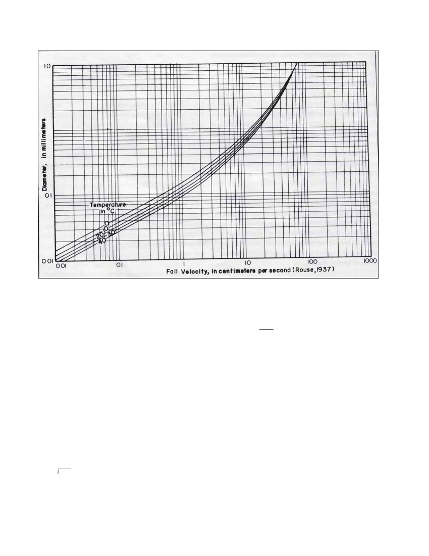
Figure 5.2 Fall velocity of quartz spheres in water
For example, dlimit = 0.2 mm should be selected in a case
where: h = 50 m, suspended particles are mostly pure quartz
or similar minerals, and a Francis turbine is used.
5.3.4 SETTLING DESIGN
The area required for the settling basin and its plan shape are
calculated as follows:
1. Using the criteria discussed in Section 5.3.3, determine
what the range of the scheme is (i.e., low, medium or high
head) and decide on the corresponding minimum particle
size to be settled, i.e. dlimit .
2. Using Figure 5.2, for the selected dlimit , determine the fall
velocity, w.
3. Calculate the required basin surface area (A) using the
following equation: A = 2Q / W Note that a factor of 2 has
been used to allow for turbulence in the basin.
4. With the basin area calculated above, fix either the length,
L, or the width, B, according to site conditions and calculate
the other dimension such that 4 ≤ L/B ≤ 10.
5. Check that the horizontal velocity (V = Q/By ) is less than
0.44 dlimit , i.e. V < 0.24 m/s
where dlimit = 0.3 mm. If not, increase the cross sectional area
(B or y) to meet this condition.
Alternatively Vetter’s equation which is commonly used in
design of small hydro settling basin in Nepal and gives
reasonable estimates of the dimensions required is also worth
mentioning here. The basic philosophy in this method is to
calculate settling efficiency for the particle size considered.
The vetter's equation to determine settling efficiency is:
Wη=hesreett,lηin=g 1ef-fei-c[iewnQ*cAyso]f a settling basin (the result is a ratio and
could be converted into a percentage by multiplying by 100)
w=settling velocity of considered particle size, m/s
As=surface area of the settling basin settling zone, m2
Q=design flow, m3/s
A 90% settling efficiency for particle size based on head as
discussed earlier would be appropriate when using Vetter’s
equation to size settling basin in micro hydro schemes. The
desired efficiency of the settling basin is achieved by finding
the surface area of the settling zone and then dimensioning
the area considering the criteria mentioned in previous
method.
A schematic diagram of a typical settling basin is shown in
Figure 5.1. Double chamber will not be required for small
flows but this arrangement will enhance the settling efficiency
and another advantage is that while sediments are being
flushed in one chamber, the other could continue conveying
flows downstream and thus half of the possible power output
can be generated instead of complete plant shutdown.
5.3.5 STORAGE DESIGN
The concentration of suspended particles in the flow can be
expressed as follows: